Using Digitizers (Methods)
|
|
Using Digitizers (Methods) |
www.CAD6.com |
|
Working with Malz++Kassner CAD6 can be made a lot easier by using a digitizer (also known as a "graphics tablet" or simply a "tablet"). A digitizer allows faster and more accurate input than a conventional mouse and the digitizer's large input area can also be used to select commands.
A tablet with a size of 12 ×12 inches (305 × 305 mm) is perfect, however for certain purposes smaller or larger tablets may be better suited. As input device you can basically choose between the mouse-like cursor or a pen. The cursor normally has at least 4 or 5 buttons but some have significantly more. A pen has usually only 3 buttons and one of these buttons is the pen's pressure-sensitive tip.
GeneralAll major digitizer manufacturers now offer drivers for Windows. A digitizer can be always used as a replacement of the standard mouse ("Relative Mode"), but a digitizer only becomes really productive when used in the so-called "Pen Mode" or "Absolute Mode" ("WYPIWYG" Mode, "where you point is where you go"). If this mode is active a certain tablet area is mapped on the screen, so that any position of the input device inside this tablet area is mapped absolutely to the mouse pointer's position on the screen. For example, if you position your input device in the lower left corner of this tablet area then also the mouse pointer is displayed in the lower left corner of the screen.
To be able to use a tablet in "Absolute Mode" it has to support the so-called WINTAB® interface. All major digitizer manufacturers (for example Wacom®, Genius®, CalComp®, and Summagraphics®) deliver along with the tablet appropriate drivers. If you have no driver for your tablet or are looking for a newer version you can download the current driver from the manufacturer's Web site.
Setting up the TabletAfter the successful installation of the tablet driver you have to specify some settings in the tablet driver's control applications. Usually you can find the corresponding shortcut in the Windows Control Panel. Although the relevant settings have different names in the various manufacturer-specific control applications, you always have to specify the settings listed below. You should not change the default values of the other settings.
After you have specified all necessary settings in the control application you should exit and restart Windows to activate them (maybe this is not always necessary but it also does no harm). Then start CAD6 and choose the commands Manage > Digitizer > Button and Tracing Options and Manage > Digitizer > Load Assignment to fit CAD6 to the tablet. The CAD6 "Digitizer" menu is only available if the tablet driver is installed properly.
Position Mode (Control Application only)Activate "Pen Mode" or "Absolute Mode" ("WYPIWYG" Mode, "where you point is where you go") respectively.
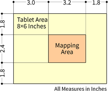
Tablet Area (Control Application and CAD6)Set the option "Portion of Tablet" or "Enable Mapping" respectively and enter the measures of the mapping area shown in the graphic corresponding to your tablet's size. For that it is important that you find out whether the measures of the mapping area in your control application have to be entered relative to the lower left or upper left corner of the tablet. You also have to enter the measures of the mapping area in the dialog of the command Manage > Digitizer > Button and Tracing Options.
In the tablet driver's control application you must enter all measures in inches (sometimes you have to specify inches as current unit first) because the tablet sizes are also given in inches. In the dialog of the command Manage > Digitizer > Button and Tracing Options all measures are specified in 1/1000 inches relative to the lower left corner. So for a 12 ×12 inches tablet you have to enter 5000 for the distance of the bottom margin.
Measures for 8 × 6 inches tablets:
Measures for 12 × 12 inches (or larger) tablets:
Screen Area (Control Application only)Activate the setting "Whole Screen" or "Complete" respectively. Sometimes you also have to enter the resolution of you screen, e.g. 1920 × 1080 pixels.
Define Buttons of the Input Device (Control Application and CAD6)5-Button Crosshair Cursor (arranged in two rows, e.g. Wacom): Button 0 Driver Settings: Left Mouse Click CAD Settings: Left Mouse Button + Command Level 1 Button 1 Driver Settings: Middle Mouse Click CAD Settings: Middle Mouse Button Button 2 Driver Settings: Right Mouse Click CAD Settings: Right Mouse Button + Command Level 2 Button 3 Driver Settings: None or Application Defined CAD Settings: Coordinate Tracing Button 4 Driver Settings: None or Application Defined CAD Settings: Coordinate Tracing
4-Button Crosshair Cursor (arranged in one row, e.g. CalComp): Button 0 Driver Settings: Left Mouse Click CAD Settings: Left Mouse Button + Command Level 1 Button 1 Driver Settings: Nothing or Application Defined CAD Settings: Coordinate Tracing Button 2 Driver Settings: Middle Mouse Click CAD Settings: Middle Mouse Button Button 3 Driver Settings: Right Mouse Click CAD Settings: Right Mouse Button + Command Level 2
3-Button Pen: Button 0 (tip) Driver Settings: Left Mouse Click CAD Settings: Left Mouse Button + Command Level 1 Button 1 Driver Settings: Double Left Mouse Click CAD Settings: Nothing Button 2 Driver Settings: Right Mouse Click CAD Settings: Right Mouse Button + Command Level 2
Load Assignment and Print Template (only CAD6)Choose the Manage > Digitizer > Load Assignment command and load one of the digitizer assignment files located in the Documents\Malz++Kassner\CAD6\Setting directory. Which file to load depends on your digitizer's size:
8 x 6 inches digitizer: DIGIT06.DIG 12 x 12 inches digitizer (or larger): DIGIT12.DIG
Finally, you should load and print the command template for your digitizer. This template contains all predefined command fields available. Malz++Kassner CAD6 normally uses only a small area in the center of the digitizer to map the screen. The remaining area is divided into small square fields, each of which is linked to a command. If a field is clicked on, the associated command is carried out as if it had been selected from the menu.
The digitizer templates are normal drawings that can be printed using the File > Print > Drawing command. Depending on the digitizer's size, load the following drawing file from the Documents\Malz++Kassner\CAD6\Setting directory:
8 x 6 inches digitizer: DIGIT06E.mkd 12 x 12 inches digitizer (or larger): DIGIT12E.mkd
Print out the drawing with the "Multiple Pages" option enabled, trim the sheets, and fasten them together with sticky tape. Place the digitizer menu under the plastic cover in the lower left corner of your digitizer.
The template also contains a graphic and a brief description on how to configure a digitizer.
Deleting or Changing the Command AssignmentIf you wish to change or delete the default command assignment, you can do so by using the Define Digitizer Command Field command. This commands is not shown in the menu but is selected by clicking on a command field on the digitizer while at the same time keeping the SHIFT key pressed.
Tracing TemplatesA common use for digitizers is tracing templates. If a cursor (sometimes with an attached magnifier) is used, it is possible to trace with an precision of up to 1/1000 inches (0.0254 mm).
Malz++Kassner CAD6 can be used for tracing by reserving a button on the input device for it. Using the Manage > Digitizer > Tracing Calibration and Manage > Digitizer > Set Tracing Origin commands the digitizer can be set up accurately for this.
Afterwards, points on the template can be transferred accurately and easily to a drawing simply by clicking on them with the corresponding button of the digitizer's input device.
|
CAD6studio Release 2025.2 - Copyright 2025 Malz++Kassner® GmbH