Object 28 "Dimension Angle" (Entity Type "Object") Changed in Version 2021.0
|
|
Object 28 "Dimension Angle" (Entity Type "Object") Changed in Version 2021.0 |
www.CAD6.com |
|
Data Block SequenceData Block 001( Start1 ) Data Block 002( End1 ) Data Block 001( Start2 ) Data Block 002( End2 ) Data Block 000( Line ) Data Block 000( Num1 ) Data Block 000( Num2 ) Data Block 000( Ext1 ) Data Block 000( Ext2 ) Data Block 110( PreText ) Data Block 110( NumText ) Data Block 110( PostText ) Data Block 110( Tolerance1 ) Data Block 110( Tolerance2 ) Data Block 225( Options )
ParametersStart1 [MKI_POINT] Start point of the first edge. End2 [MKI_POINT] End point of the first edge. Start1 [MKI_POINT] Start point of the second edge. End2 [MKI_POINT] End point of the second edge. Line [MKI_POINT] Dimension line position. Num1 [MKI_POINT] Position of the dimension text. Num2 [MKI_POINT] Direction of the dimension text. Ext1 [MKI_POINT] First dimension extension line definition. Ext2 [MKI_POINT] Second dimension extension line definition. Prefix [MKI_STRSHORTW] Prefix text for the dimension. Value [MKI_STRSHORTW] Dimension text for the dimension. Postfix [MKI_STRSHORTW] Postfix text for the dimension. Tolerance1 [MKI_STRSHORTW] Upper tolerance text for the dimension. Tolerance2 [MKI_STRSHORTW] Lower tolerance text for the dimension. Options [MKI_DIMLARGE] Dimension parameters.
Prefix, Value, and Postfix will be connected to one text ("Main dimension text") without separating characters.
Attributes New in Version 2021.0An angle dimension may contain attribute data blocks (see MKI_BLOCK_ATTRIBUTE) only of type "local". They must be placed behind all other datablocks. Attributes of types "outline" and "point" must not exist. The total number of local attributes per object is limited to MKI_ATTRIBS_PER_OBJECT.
Specific Usage of Data Block 225DimFlag, New in Version 6.51 LineOrientation, LineDimType [__int32] Unused. LineDistMode [__int32] The value LineDistMode determines how the dimension line's distance to the dimension is calculated. The distance is always measured relative to the one of the edge's end-points that is farest away from the virtual (or real) intersection point of the two edges. Possible values are:
MKI_DIMDISTANCE_ARBITRARY The dimension line passes through the point Line.
MKI_DIMDISTANCE_FIXED The dimension line has exactly the distance stated in LineDistance to the edge's end-point. The position of Line determines what partial angle to use.
MKI_DIMDISTANCE_MULTIPLE The dimension line's distance is a multiple of the value stated in LineDistance, while being as close as possible to Line. The position of Line determines what partial angle to use.
Example|BlockType| 0,225,0,0, |TextFont| 0,0,400,"DINLQ", |TextXProperty| 1,1,0,0.0/0.0/0.0,0.0/0.0/0.0,0.0,0,0, |TextSize1,TextSize2| 5.0,3.5, |CharDistance,TabDistance,TextMode,TextOrder| 0,4,1,0, |Precision,Refresh,Centered,Tight,Rotate| 2,1,1,1,0, |ArrowStart...,ArrowEnd...| 1,0,1,0, |ExtStartDisplay,ExtEndDisplay,LineDisplay| 1,1,1, |Orientation,Type,DistMode,Distance| 1,1,1,10.0,0.0, |System| 0;
This angle dimension will be lettered with the font "DINLQ", using pen 1. The main dimension has a text size of 5 mm, the tolerances have a text size of 3.5 mm. The dimension number will automatically placed centered and tight to the dimension line, it will be updated automatically. The dimension line has a fixed distance of 10 mm to the edge's end-point. Both dimension extension lines will be visible, they are drawn radially from an edge's end-point to the dimension line. At both ends of the dimension line, a filled, non-rotated, triangular arrow will be drawn. The dimension will be calculated according to the settings in the coordinate system 0 ("- Standard -").
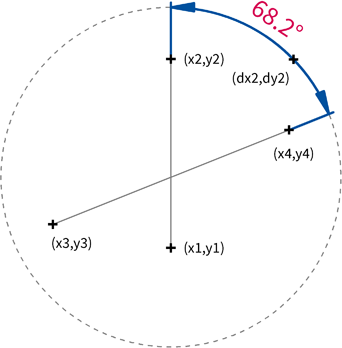
The image above shows an angle dimension created using the settings described above. The points Start1, End1, Start2 and End2 define the two edges of the angle. The dimension line has a distance of 10 mm to the point End2. The dimension number was centered and set tight automatically, so the point Num1 is irrelevant. As the number is not rotated the point Num2 is not used.
The orientation of the two edges together with the dimension line definition point Line determines which of the possible eight angles is to be measured. As End1 is above Start1, the dimension starts above the virtual intersection point. As End2 is right to Start1, the dimension ends right to the virtual intersection point. This constellation still allows two angles - one running clockwise from top to right, one running counter-clockwise. Now the dimension line definition point Line determines which one to choose. In this case it is the angle running clockwise, i.e. the smaller angle at the upper right.
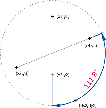
The image above shows a similar angle dimension, but the end-points of the first edge are placed vice versa. As Line now lies below Start1, the dimension starts below the virtual intersection point. According to the dimension line definition point Line, the lower right angle is to be measured.
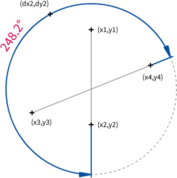
The image above shows another similar angle dimension but now dimension line definition point Line was placed somewhere else, so now the upper left angle is measured.
The two edges of the angle do not have to intersect directly even though they do in all examples shown here. In any case a "virtual" intersection point is calculated, i.e. the intersection of the edges extended to endless lines. If both edges are parallel no dimension is displayed!
Interface Command SequenceMKI_ObjectOpen, Type = MKI_OBJ_DANGLE MKI_ObjectAddPoint, Type = MKI_DB_POINT_START MKI_ObjectAddPoint, Type = MKI_DB_POINT_END MKI_ObjectAddPoint, Type = MKI_DB_POINT_START MKI_ObjectAddPoint, Type = MKI_DB_POINT_END MKI_ObjectAddPoint, Type = MKI_DB_POINT_ANY MKI_ObjectAddPoint, Type = MKI_DB_POINT_ANY MKI_ObjectAddPoint, Type = MKI_DB_POINT_ANY MKI_ObjectAddPoint, Type = MKI_DB_POINT_ANY MKI_ObjectAddPoint, Type = MKI_DB_POINT_ANY MKI_ObjectAddTextShort, StaticLength = false MKI_ObjectAddTextShort, StaticLength = true MKI_ObjectAddTextShort, StaticLength = false MKI_ObjectAddTextShort, StaticLength = false MKI_ObjectAddTextShort, StaticLength = false
Use the MKI_PARSE_OBJ_DANGLE class to parse the data blocks of such an object in memory.
|
CAD6interface 2026.1 - Copyright 2026 Malz++Kassner® GmbH