Line > Angle Bisector (Temporary Objects Menu)
|
|
Line > Angle Bisector (Temporary Objects Menu) |
www.CAD6.com |
|
This command is used to create a Temporary Object as a line which runs along the bisector of the angle between two lines of any type.
Any line in an existing object can be identified as a reference line. This can also be a side of a rectangle or a leg of a circle segment.
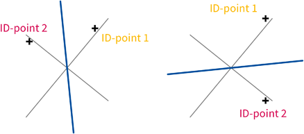
The position at which the line was identified (the "ID Point") is important for the rest of the procedure. Together with the position at which the second line is identified,it determines which of the two possible angle bisectors should be used (see below).
Any line in an existing object can be identified as the second reference line. This can also be a side of a rectangle or a leg of a circle segment.
The position at which the line was identified (the "ID Point") is important for the rest of the procedure. Together with the position at which the first line is identified, it determines which of the two possible angle bisectors should be used (see graphic).
After identification of the second line, a straight line which runs through the ID point determining the angle bisectors appears. This line is referred to as the "Reference Straight Line".
The start point of the line can be entered by clicking the mouse anywhere in the drawing. A perpendicular is dropped from this point to the reference straight line to determine the start point of the new line.
The end point of the line can be entered by clicking the mouse anywhere in the drawing. A perpendicular is dropped from this position to the reference straight line to determine the end point of the new line.
|
CAD6studio Release 2025.0 - Copyright 2025 Malz++Kassner® GmbH