Block > Create Block Creation Procedure, Frame - Point (Library Menu)
|
|
Block > Create Block Creation Procedure, Frame - Point (Library Menu) |
www.CAD6.com |
|
This command can be used to create a block creation procedure. After selecting the area to make up the block, a frame and the insertion point are entered.
You cannot directly create a block creating procedure with a polygonal section. If you require one, first use this command to create a block creation procedure with a rectangular section and all required settings, then call Manage > Procedures for Automation and use "Re-enter polygon" there to replace the rectangular section with a newly entered polygonal section.
The first corner point of the object selection area can be entered using the mouse, by clicking anywhere in the drawing. This corner point also shows the block's insertion point.
The object selection area's second corner point can be entered using the mouse, by clicking anywhere in the drawing.
The first corner point of the block frame can be entered using the mouse, by clicking anywhere in the drawing.
The block frame's second corner point can be entered using the mouse, by clicking anywhere in the drawing.
The block's insertion point can be entered using the mouse, by clicking anywhere in the drawing. The insertion point should be placed at a distinct place in the block, e.g. at the end point of a line or the corner point of a rectangle.
After entering the insertion point, the "Create Block" dialog appears, in which the name of the block to be generated can be entered. In addition, some parameters can be specified.
Afterwards, the "Edit Procedure" dialog appears in which the name and parameters of the procedure are entered.
Blocks may themselves contain instances of other blocks and groups, i.e. nested instances are possible. This makes it possible, for example, to create components made up of components from several blocks from different libraries. There are however two restrictions, which should help avoid problems:
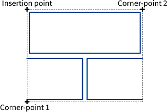
Notes on Blocks for HatchingsIn the case of a block that is to be used for hatching, the two corner points should define the overall frame of the repeated area, i.e. determine its horizontal and vertical dimensions (see graphic).
The insertion point should be on or within the frame and defines the position of the hatch block relative to the respective hatch origin.
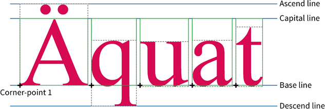
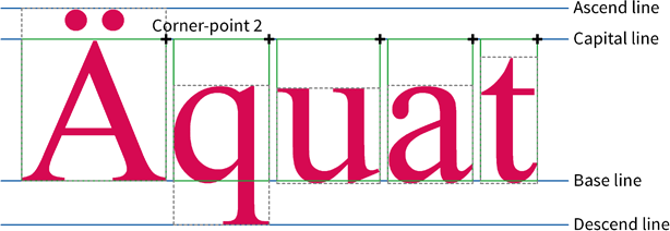
Notes on Blocks for Font CharactersFor a font character, the first corner-point must be the left limit on the baseline of a character (see graphic). This point does not have to be on the frame surrounding the block.
The second corner-point should be the right limit of the character at the height of a capital A (ascend line, see graphic). This point does not have to be on the frame surrounding the block.
The insertion point should be placed identically to the first corner-point (see first graphic), but in any case on the baseline.
|
CAD6studio Release 2025.0 - Copyright 2025 Malz++Kassner® GmbH