Snapping Functions and Compound Measurements (Tutorial)
|
|
Snapping Functions and Compound Measurements (Tutorial) |
www.CAD6.com |
|
This chapter uses some commands that are only available in CAD6studio and/or CAD6industrie!
AimThe following example shows ways in which the Construction Aid and snapping functions can be used and in addition how to set dimension parameters to cope with making complicated measurements.
SettingsTutorial.mkd
ProcedureFirst of all, the rectangles are drawn and hatched, then rotated and measured.
This drawing does not contain any information about the height of the rectangles. You can choose any height you want as the principle remains the same. However, it is necessary to stick to a predetermined width and this is done with the help of the Construction Aid. Use the command Construct > Construction Aid Endless Line > Vertical to place a first vertical Construction Aid endless line at the left of your page.
Use the command Construct > Construction Aid Endless Line > Parallel, Numerical to insert another vertical line parallel to the existing one. After choosing the command, a dialog appears in which you can enter the required spacing. Enter 40 mm (the width of the first rectangle) and identify the previously drawn vertical. Move the crosshair to the right until the red line separates from the identified line and jumps 40 mm to the right. Confirm this by clicking the left mouse button and then end the command sequence (click right mouse button, and if the Workflow Manager is active and appears, choose Finish Command. Alternatively, the corresponding button in the Parameter Window can be clicked).
Because the parallel lines are placed in the correct positions automatically, snapping must remain turned off during this command. Otherwise, conflicts can arise between the different positioning techniques. If the result of the poisoning leads to a conflict, the loudspeaker beeps.
To reactivate the Construct > Construction Aid Endless Line > Parallel, Numerical command, press SHIFT and ESC at the same time, then press the "Options" button. The same dialog as before appears and you can set the value 20mm for the second line's spacing. Proceed as previously: identify the last line and move the crosshair until the red line jumps 20 mm to the right. Click the mouse button to confirm this and move the crosshair again until the line jumps another 20 mm, click the left mouse button to confirm the command. Then end the command sequence (click right mouse button, and if the Workflow Manager is active and appears, choose Finish Command. Alternatively, the corresponding button in the Parameter Window can be clicked).
After pressing SHIFT+ESC and the button "Options" again, enter the last interval of 50 mm and proceed as previously.
Figure 1: Construction Aid
To finish constructing the Construction Aid use the command Construct > Construction Aid Endless Line > Horizontal to place a horizontal line in the lower part of the page. The Construction Aid should resemble Figure 1.
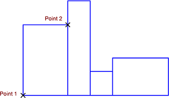
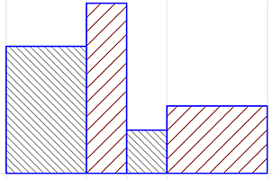
To draw the first rectangle, activate snapping and the "Construction Aid" snapping mode. Choose Draw > Polygon > Rectangle and click on the intersection of the left Construction Aid endless line with the horizontal Construction Aid endless line (Point 1, Figure 2).
Because you can choose the height of the rectangle freely and only have to place the rectangles second corner on the second vertical line, activate the "Edge" snapping mode and then place the second corner point on the vertical Construction Aid endless line which you previously placed exactly 40 mm to the right. (Point 2, Figure 2).
Use a similar method to draw the second, third and fourth rectangles (Figure 2).
Figure 2: Basic elements
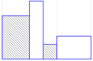
Next, hatch the rectangles. Apart form the standard hatching in rectangles 2 and 4, it's necessary to define a narrower -45° hatching for rectangles 1 and 3.
To do so, choose Draw > Hatching > Edit Hatching Types and create a new hatching type by right-clicking into the list and choosing "New". Enter Hatching Two and click on "OK". Double-click the new list entry to edit it. On the appearing dialog, set the distance to 2.5mm and the orientation to -45°. Close the top-level dialog by clicking on "OK", then click the rad framed arrow in front of the new hatching type to activate it, and then close the main dialog.
The new hatching becomes the current hatching. Choose Draw > Hatching > Objects and click on the first and third rectangle (Figure 3).
Figure 3: First hatching
To re-select standard hatching, choose Draw > Hatching > Edit Hatching Types and select "- Standard -" hatching type from the list which appears.
Rectangles 2 and 4 can now also be hatched easily by choosing Draw > Hatching > Objects (also available from the command list, simply press the key H) and clicking on them (Figure 4).
Figure 4: Second hatching
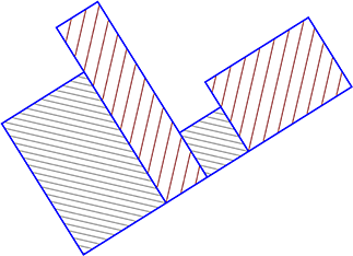
Next, all the objects are to be rotated by 32°. To do this, choose Modify > Rotate Objects > Center. and identify the objects to be rotated. In this case all the objects on the page are to be rotated, and it is easiest to identify them all by using the function key F10 (or the keyboard combination SHIFT+Q). Alternatively, you can hold down the SHIFT key and drag a frame around all the objects. Enter 32 into the dialog which appears and click on "OK" (Figure 5).
As the Construction Aid is not required any more, it can be turned off by pressing the F9 key or clicking on the relevant button in the panel. This makes the drawing clearer.
Figure 5: Objects after rotation
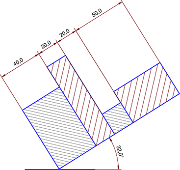
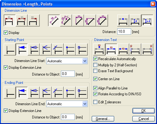
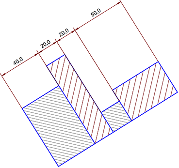
The dimensions are now applied. The starting point is to be the longest rectangle. The dimension should be at least 10 mm from the top edge of the highest rectangle. All the other dimensions will align themselves to this dimension. Choose Annotate > Dimension > Length, Object. Now, press SHIFT+ESC and the "Options" button.
This calls a dialog (Figure 6) where you can specify various options for the appearance and positioning of the dimension line, the start and end points and the positioning of the dimension figure.
Figure 6: Dialog "Dimension > Length, Object"
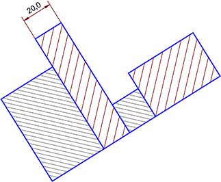
Identify the segment to be measured and move the mouse towards the dimension line until it blends with the red dimension line. Confirm this by clicking the left mouse button (Figure 7).
Figure 7: Measuring the first rectangle
It is necessary to alter the settings for the subsequent measurements. Either call the command Annotate > Dimension > Length,Object again or press SHIFT+ESC. This key combination restarts the command and calls the dialog again. To align the dimension lines correctly, it is not possible to use a fixed distance; choose the icon for user-defined spacing (see picture) and close the dialog by clicking on "OK".
Figure 8: Icon for user-defined spacing
Identify one of the three lengths which still has to be measured. The dimension line can be moved freely. To position it accurately, choose "Corner/Endpoint" snapping mode from the panel and press the F6 key to turn snapping on. Four small lines marking the snapping radius appear round on the crosshairs. Click on the intersection of the existing dimension line and the existing extension line to position the new dimension line (Figure 9).
Figure 9: Zoom of the snap point
The new dimension line will snap into place correctly aligned with the other dimension line. Proceed in a similar way for the remaining dimension lines. You can now turn snapping off again, either by pressing F6 or by clicking on the button in the panel. In many cases, it can make more sense to temporarily turn snapping on or off by holding down the SHIFT key. Try both methods. Your drawing should now look like this:
Figure 10
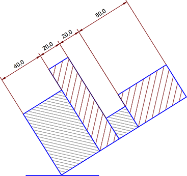
Next the base line will be drawn in. This is done in two steps. Choose Draw > Line > Horizontal and specify the starting point of the line. After clicking on the status window or pressing the F8 (ENTER) key a field appears into which a coordinate length or radius can be entered. By default, a "sensible" value is already entered. Enter 50 mm as the length. Choose Modify > Move Objects > Offset and identify the horizontal line which you have just drawn. Next it is necessary to enter a reference point. To place this exactly in the middle of the line, activate "Midpoint" snapping mode and click on the line. You have "grabbed hold" of the center of the line and can move it about. The line's midpoint should be placed on the bottom corner of the first rectangle. Activate "Corner/Endpoint" snapping mode (you may have to turn off the old snapping mode) and click on the corner (Figure 11).
Figure 11: Baseline
Finally, the angle between the baseline and the rectangle will be added to the drawing. Choose Annotate > Dimension > Angle, Line - Line and identify the ends of the two lines enclosing the angle. You can now choose from multiple angles by moving the crosshair. If you want to dimension an angle larger than 180°, keep the CTRL key pressed.
In a similar way to measuring lengths, a extension line appears at a fixed radius from the center of the angle. Confirm the dimension line position 40 mm from the center of the angle (one "jump" = 10 mm) (Figure 12).
Figure 12: Angle between the baseline and the rectangle
Save your drawing using File > Save Drawing as.
|
CAD6studio Release 2026.0 - Copyright 2026 Malz++Kassner® GmbH