The Rectangle (Tutorial)
|
|
The Rectangle (Tutorial) |
www.CAD6.com |
|
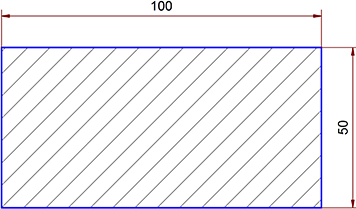
Figure 1: The Rectangle
AimA rectangle of fixed size is to be drawn, measured, hatched and centered on the page.
SettingsTutorial.mkd
Firstly, draw the rectangle to size. Choose the pen "0.5 mm\Solid Line Wide", which has the correct set of properties (solid line, 0.5 mm) for object edges.
Choose Draw > Polygon > Rectangle menu. The status window gives you information about the progress of the command. Follow the prompt "Enter Corner 1" and click the left mouse button at the upper left of the page. It can be released immediately. The position of this point is not really important as the rectangle is to be centered on the page anyway. This mouse click has provisionally marked the upper left corner of the rectangle.
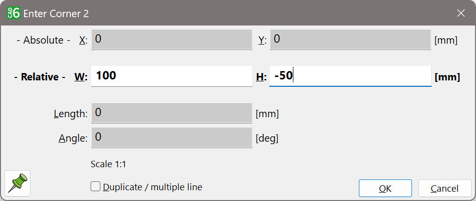
The status window now prompts you to enter the second corner point. As this point is to be at a precisely determined x and y distance (also called a relative distance) from the first corner point, enter this distance with the keyboard by pressing the ENTER key. A dialog appears. Move the field and the insertion mark to the W field of the dialog by pressing the TAB key multiple times, type 100, move the mark to the next field H, type -50 and press ENTER again.
Figure 2: Direct Input
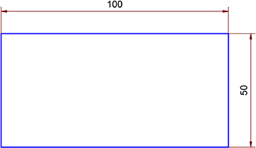
This tells the application to enter the second corner point 100 mm in the x direction and -50 mm in the y direction from the first corner point. Now you have a rectangle of the right dimensions (Figure 3). The dimensions can be checked by measuring the object.
Figure 3
If you have already chosen a pen for dimensions using Manage > Pens > Defaults it is not necessary to change pens. If this is not the case, choose the pen "0.25 mm\Solid Line Narrow" from the panel.
Choose the command Annotate > Dimension > Length, Object. The dialog contains dimension parameters for most situations. Confirm these settings by clicking on "OK". The status window now prompts you to identify a reference line. This line is the line which is to be measured. Click on the upper horizontal line of the rectangle with the left mouse button. This identifies the line. Next, specify the dimension line position by moving the mouse vertically (perpendicular to the reference line). You will see that the dimension line always moves in fixed increments. Click the left mouse button when the line has jumped one position upwards. This completes the first measurement.
Without re-starting the command (it is still active) you can measure the right (vertical) side of the rectangle in the same way (Figure 4).
Figure 4
Next, apply a hatching to the rectangle. Activate the pen "0.25 mm\Solid Line Narrow" and choose the Draw > Hatching > Objects command. To apply the hatching, identify the rectangle by clicking on its edge (Figure 5).
Figure 5
Finally, choose Modify > Align Objects > Centered, Page Both and press F10 to center the whole drawing relative to the page margins. Choosing Manage > Zoom > Page allows you to see the effect properly.
To save your first drawing, choose File > Save As, enter a file name, e.g. Drawing1.mkd, and click on "OK". You can then enter a full description of the drawing in a further dialog and carry out the save by clicking on "OK".
|
CAD6studio Release 2025.0 - Copyright 2025 Malz++Kassner® GmbH