Model Space and Pages (Basics)
|
|
Model Space and Pages (Basics) |
www.CAD6.com |
|
Before starting a new drawing, it is often necessary to specify the page format for the drawing. To do this, choose Manage > Pages > Edit. This calls a dialog where you can either choose a standard page format or a custom page format by double-clicking onto one of the defined pages. The page orientation is also specified in this dialog.
Malz++Kassner CAD6 supports a Model Space and up to 1000 pages in each drawing. Using those, drawings can be structured in different ways depending on complexity and personal liking.
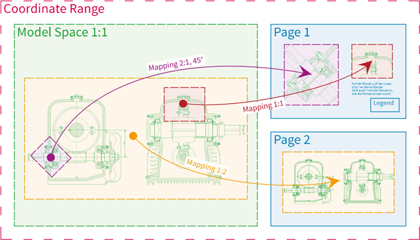
Model Space and Pages Independent of Each OtherIf a drawing depicts a "Model" (e.g. a component, a machine, a ground plan, etc.) of which multiple sections shall later be printed at different places on the paper, maybe even using different scales, it is advisable to place the model completely into the Model Space in order to map parts of it onto the pages later. Here is a schematic view:
All objects of the model are assigned to Model Space (green). Independent from the final output, the model is usually designed in original size (1:1 scale). Once the drawing of the model has been sufficiently finished, parts of the model will be mapped into one or multiple pages (blue) using Mapping objects. In the respective pages, objects will be added that are either scale-dependent (such as dimensions) or part of the page's layout (such as legends and drawing frames).
Mappings dynamically project a section of the Model Space within a page (like the image of a supervision camera). Once the Model Space's content changes, the mappings will change, too (at the latest during the next screen redraw). Mappings must always be assigned to pages (not to the Model Space), the objects to be mapped must be part of the Model Space. The objects visible within a mapping can be chosen for purposes such as snapping points or drawing parallels, but they cannot be modified directly. This is only possible in the Model Space.
Since objects in the Model Space and objects in pages are completely independent from each other, they can very well share the same coordinate range, resulting in logical, stacked planes. You can switch between these planes by switching the current page. Here is a schematic view:
In order to use and output this structure in a sensible way, the following display and output settings should be adjusted:
•Option Manage > Page Display > Layout (Active Page / Model).
•Command Manage > Drawing Settings > Output, setting "Output of objects based on their page assignment":
Furthermore, Manage > Pages > Edit should be called. There, right-click into the list of pages and activate the option "Auto-Assign New Objects to Active Page" so that it is checked.
This structure is normally used when importing DXF and DWG drawings.
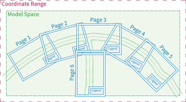
Pages as Model Space Dividers / Multiple Independent PagesIf the drawing consists of one huge, contiguous model (such as a land register plan, a hall plan, etc.) that shall be printed onto multiple pages, the pages can be used to divide up the Model Space by placing them above the Model Space like punching forms. The pages can be rotated and/or scaled individually. Here is a schematic view:
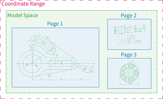
For multiple, independent models (e.g. a collection of separate components), the same structure can be used, but with non-overlapping pages. Here is a schematic view:
In order to use and output this structure in a sensible way, the following display and output settings should be adjusted:
•Option Manage > Page Display > Active Page + Model.
•Command Manage > Drawing Settings > Output, setting "Output of objects based on their page assignment":
Furthermore, Manage > Pages > Edit should be called. There, right-click into the list of pages and clear the option "Auto-Assign New Objects to Active Page" so that it is unchecked.
In this case, it may be useful to define a separate coordinate system for each page (Manage > Coordinate Systems > Edit) in order to be able to set origin and scale independent for each page. The respective coordinate system can be assigned to its page so that is will automatically be activated when switching between pages.
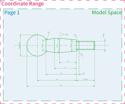
One PageSimple drawings that easily fit onto one printer's page can be created completely in model space as long as they lie inside the one page's extents. Here is a schematic view:
In order to use and output this structure in a sensible way, the following display and output settings should be adjusted:
•Option Manage > Page Display > Classic (All).
•Command Manage > Drawing Settings > Output, setting "Output of objects based on their page assignment":
Furthermore, Manage > Pages > Edit should be called. There, right-click into the list of pages and clear the option "Auto-Assign New Objects to Active Page" so that it is unchecked.
|
CAD6studio Release 2025.0 - Copyright 2025 Malz++Kassner® GmbH