3D Set Operations (3D Introduction)
|
|
3D Set Operations (3D Introduction) |
www.CAD6.com |
|
The operators "Union", "Intersection", and "Difference" can be used to assemble extremely complex parts from multiple simple elements. But they can only work correctly if the input data is correct, too.
Every numerical computer program has one big problem: the numerical accuracy of computers is limited. Usually, calculation are done with 14 fractional digits. At first, this seems enough, but in the final analysis, any limitation to the accuracy (whether to 14 or 100 fractional digits) is insufficient in many cases. Especially during set operations, many "is equal" and "is not equal" decisions have to be made. Due to the limited accuracy, these decisions can never be made exactly. This problem mainly affects situations where parts do touch (but not overlap). That’s why here are some recommendations on how to bypass this limitation:
Express Yourself ClearlyTo avoid ambiguities, you should unmistakably align parts used as input for set operations so that they either overlap clearly or that they do not touch at all.
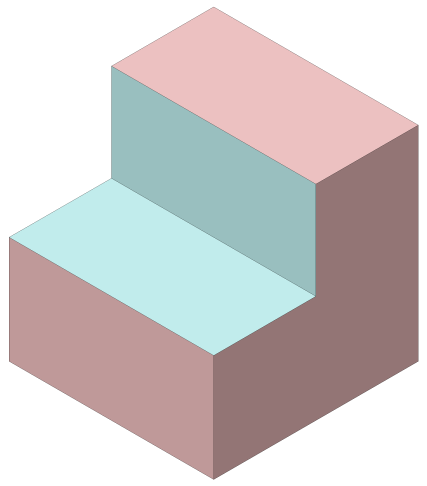
Let’s look at a simple example: A cuboid shall be subtracted from a cube. Assuming a perfect operation, the source parts and the corresponding result would look as follows:
Source Parts
Desired Result of the Difference
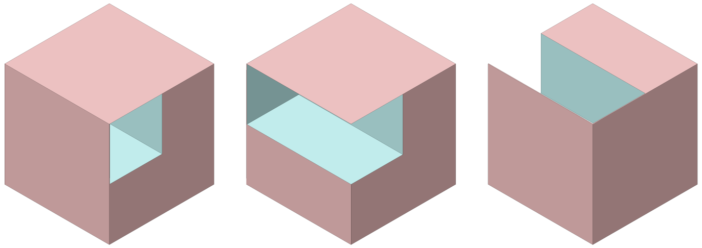
But since both parts are the result of multiple calculations and some movements, these two parts will never be aligned exactly but only pretty close to exact. Thus, the result of the difference might also be one of the following:
Possible Erroneous Results of the Difference
None of these results are really useful.
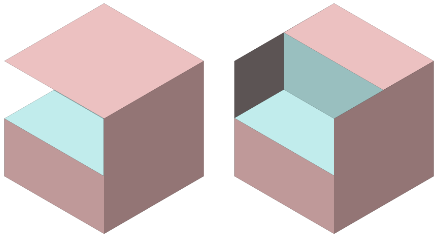
Your best option to avoid this problem from the beginning is to design the cuboid significantly larger and place it clearly overlapping with the cube:
Clearly Overlapping Parts
This avoids all situations in which part facets touching each other can result in misinterpretations.
It is easy to remember this principle by imagining that these operations will be performed by a milling machine. You would never try to mill out the light blue cuboid by having the milling cutter start exactly aligned with the outer edge of the red part, but would instead have the milling cutter approach from the outside to avoid burrs. Using the same method will avoid errors in set operations.
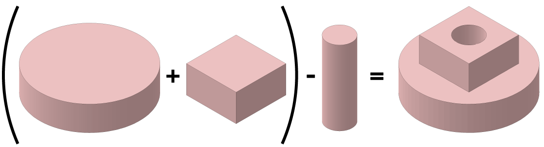
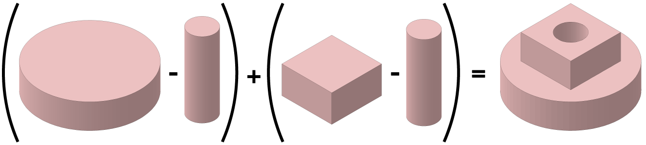
Avoid Using Operations TwiceAnother "problem" with set operations (but this time not caused by limited accuracy) is an unfavorable sequence of operations. In the following example, a part shall be created in multiple steps:
Part to be Created
Obviously, there are at least two approaches to creating the desired part from standard parts (two cylinders and one cuboid). The first approach starts by combining the larger parts using a union. Afterwards, they are together drilled through using the cylinder and a difference:
Approach 1
The second approach starts by drilling through the larger parts (each using a difference) and continues with combining the results by means of the union:
Approach 2
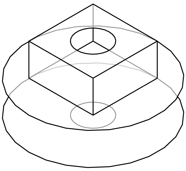
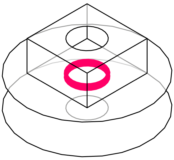
Upon first sight, both approaches are correct. Nevertheless, there is one significant difference that will not become visible unless only the edges of the created parts are displayed:
Result of Approach 1
Result of Approach 2
The second approach creates a superfluous (and in many cases very annoying) additional edge within the drill hole at the location where the two larger parts were combined (highlighted in red in the figure).
In such cases, you should always choose the approach that avoids duplicate operations!
This principle can also be remembered easily by imagining that these operations will be performed by a milling machine. If you would first drill through the larger parts and then assemble them, there would be an unintentional sharp edge inside the hole. So you would first assemble the parts and then drill through them together.
|
CAD6studio Release 2025.1 - Copyright 2025 Malz++Kassner® GmbH