Aligning 3D Parts (3D Introduction)
|
|
Aligning 3D Parts (3D Introduction) |
www.CAD6.com |
Point to PointThe easiest way to align two parts is by means of the 3D > Move / Copy 3D Parts > Point - Point command. This will simply place one point of the chosen parts onto another point or 3D construction point.
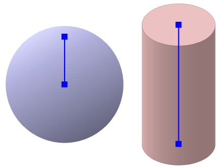
ExampleUse 3D > Create 3D Parts > Standard Part to create a sphere with a radius of 20 mm and a cylinder with a radius of 12.5 mm and a height of 50 mm:
Created Parts Before Alignment
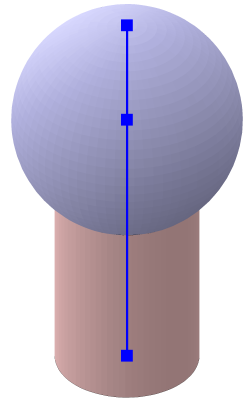
Now choose 3D > Move / Copy 3D Parts > Point - Point, choose the sphere, identify the sphere’s center point, and then the axis end point of the cylinder:
Aligned Parts
Since the sphere’s center point shall be placed exactly on the end point of the cylinder’s axis, this alignment method is extremely efficient.
Edge to EdgeAnother method of alignment is to align two edges (usually one inside the chosen part and one other) to each other. This is done by means of the 3D > Align 3D Parts > Edge - Edge command. Using this method, it is easily possible to place a perpendicular drill hole into an tilted part.
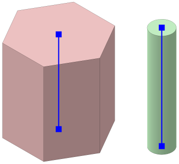
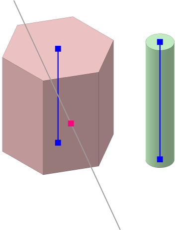
ExampleUse 3D > Create 3D Parts > Standard Part to create a prism with 6 sides, radius 10 mm and height 20 mm, and a cylinder with radius 2.5 mm and height 25 mm. Place them next to each other:
Created Parts Before Alignment
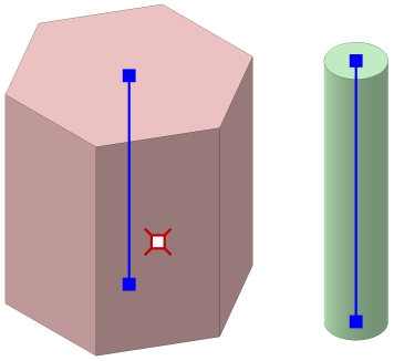
Next, choose 3D > 3D Construction Point > Center Point to determine and mark the center point of the prism’s font-most facet. Identify two diagonally opposite corner points of this facet:
Marked Center Point of the Facet
Now a construction line is created by means of 3D > 3D Construction Line > Perpendicular to Surface. First identify the prism’s facet, then identify the newly marked center point as reference point. Afterwards, the marking of the center point is no longer required and can be deleted.
The result should look as follows:
Construction Line Perpendicular to Prism Facet
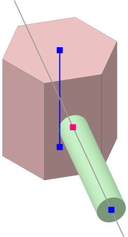
This is the moment when we use 3D > Align 3D Parts > Edge - Edge to align the cylinder on the construction line. Choose the cylinder first, then identify its rotation axis, and finally identify the construction line:
First Aligment Step
Now all we have to do is move the cylinder along the construction line using 3D > Move / Copy 3D Parts > Along Edge and combine the two parts to get the final result:
Final Part (rotated for a better view)
Planar View of PlaneThe 3D design often takes place in 2D, aligned to a surface in 3D. The 3D > Change View > Horizontal View of Chosen Edge and 3D > Change View > Planar Front View of Chosen Plane commands help here.
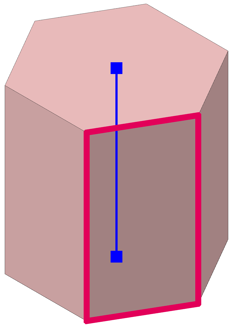
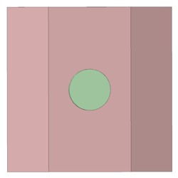
ExampleLike before, use 3D > Create 3D Parts > Standard Part to create a prism with 6 sides, radius 10 mm and height 20 mm. Choose 3D > Change View > Planar Front View of Chosen Plane and identify the face highlighted in red:
Identify plane
The view is changed so that this plane can be seen planar from the front:
Planar View of the Plane
Select the working mode 3D > View Preset > Work in View Plane so that newly created components are automatically placed in the current view plane. use 3D > Create 3D Parts > Standard Part to create a cylinder with a radius of 2.5 mm and a height of 25 mm. Place this in the middle of the surface displayed planar:
Cylinder placed onto the Surface
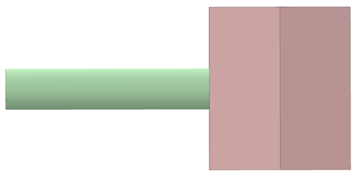
Rotate the view 90° left or right (e.g. with 3D > Change View > Rotate Positive around Vertical Axis) to see where the cylinder is located relative to the prism:
Side View
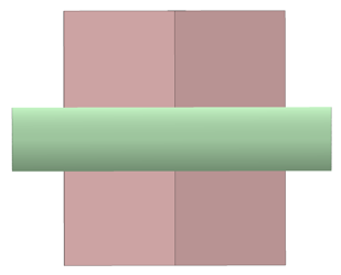
Move the cylinder "into" the prism so that it overhangs on both sides. This move can be done with normal 2D move because the work mode "Work in View Plane" is active:
Moved Cylinder
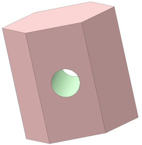
Finally, combine the two components using 3D > Edit 3D Parts > Difference (A=A-B):
Final Part (rotated for a better view)
|
CAD6studio Release 2026.1 - Copyright 2026 Malz++Kassner® GmbH