Working in 3D is Different (Creating a 3D Part)
|
|
Working in 3D is Different (Creating a 3D Part) |
www.CAD6.com |
|
Working in 3D has one main disadvantage over working in 2D: Almost any input or output device is in principle only 2D capable. Even though we are able to see things three-dimensionally, this ability is limited by a 2D monitor. As a result, it is very difficult for us to correctly determine the position of two parts relative to each other.
Let’s RotateIn order to more or less keep track of the spatial layout, it is important to frequently rotate the 3D world. This will help you to determine the positions of all currently handled objects. The easiest way to do so is the 3D > Orbit command which is also available though the following button in the Plug-In window:
"Orbit" Button
Use it extensively - this will help to avoid mistakes! Once you have finished working on a specific step, you can use one of the following buttons to switch back to one of the default views:
"Default Views" Buttons
You can also use the following buttons to revisit previews view and return the current view later on:
"Undo View Change" and "Redo View Change" Buttons
Or you can use the following buttons to save the current view before starting to work and to restore it afterwards:
"Save Current View" and "Retrieve Saved View" Buttons
Take some time to experiment with these commands, and you will realize how much your overall understanding of the 3D world will profit from rotating.
Snapping is MandatoryIn contrast to working in 2D, you will not be able to just click anywhere, anytime when working in 3D. Entering a 3D point by clicking somewhere is ambiguous in principle, since at any time there are an infinite number of possible 3D coordinates being projected to the same 2D coordinates. That’s why 3D points are always either snapped or entered by numeric coordinate entry.
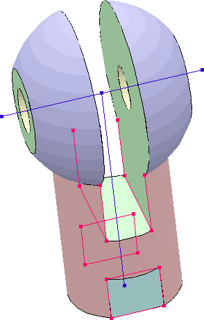
In order to facilitate the detection of corner points in 3D, you can use 3D > Options to explicitly display corner points of 3D parts (similar to definitions points in 2D). The same applies to edges and axes. Especially in complex parts, not everything that looks like an edge or a corner point can be snapped or identified. In the following figure, all axes, corner points and edges are being highlighted:
Display of Axes, Points and Edges
You can see that only a few edges (highlighted in red) can be identified. All other "edges" are curved and do not have a defined direction. In addition, the rotation axes of the two cylinders (highlighted in blue) are available. If points and/or edges required for you work should not be available, you can easily determine them using the 3D construction.
If you want to have all edges and corner points available (even those lying on curved outline elements), you can set the "Corner Threshold Angle" in operators or during the STL import to 0 degrees.
|
CAD6studio Release 2025.0 - Copyright 2025 Malz++Kassner® GmbH