Data Structure (3D Introduction)
|
|
Data Structure (3D Introduction) |
www.CAD6.com |
|
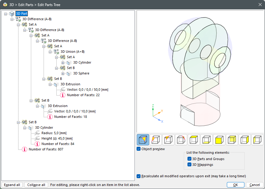
3D parts are organized in multiple layers to gain a maximum flexibility. This distinguishes them from the known structure of 2D objects. Each 3D part or group of 3D parts consists of a "header" and an attached list of elements that form the actual part. If a part consists of groups and/or operators, this results in a complex parts tree with multiple nodes and elements. Using the 3D > Edit Parts Tree command, you can view the structure of such a complex part, and, in most aspects, edit it directly:
Parts tree of a complex part
By right-clicking a single element in the parts tree you can (depending of the element’s type) view and edit its name, its parameters, its properties and its relative resolution used for the display. For standard parts and operators, it is even possible to subsequently change their type. As a result, you can change a cylinder into a hollow pipe or to change a union into a difference.
In addition to the list of elements, each part contains an additional, precalculated list of 2D surface that are used for the display of the 3D part in the 2D drawing area. This list will always be recalculated and sorted if the view of the respective part changes. The 2D surfaces will always be sorted in a way that the part in itself will be displayed correctly. If multiple parts overlap each other in the current view, their respective display order can be "wrong" so that parts that actually lie in "front" are overdrawn by parts that actually lie farther "behind".
To avoid this, parts can be integrated into a group of parts. Within a group of parts, all 2D surfaces of all contained 3D parts will be calculated jointly to avoid incorrect overlapping. This will, however, increase the required calculation time significantly! In complex scenes it is therefore better to work with separate parts and to correct their display order in the end using the 2D commands for display order control.
|
CAD6studio Release 2025.0 - Copyright 2025 Malz++Kassner® GmbH