Terms (3D Introduction)
|
|
Terms (3D Introduction) |
www.CAD6.com |
|
The 3D part introduces some the terms which shall be explained here.
3D PartIn its use, a 3D part is equivalent to an object in the 2D drawing. It is the smallest unit that can be selected by clicking with the mouse in order to be, e.g., copied or rotated. Each 3D part is assigned to specific 3D space (see below). Some examples for 3D parts are:
Cube
Group of extrusions
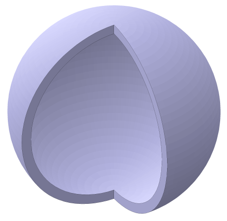
Hollow sphere segment
Result of multiple operators
These examples illustrate that 3D parts can have a varying complexity. More complex parts usually consist of multiple simple parts which are derived from 2D objects. The cube, e.g., is an extruded square, the hollow sphere segment is a rotation solid created from a connection of two circular arcs:
Cube as extrusion
Hollow sphere segment as rotation
These simple parts can then be combined by either grouping them or by using an operator (e.g. "Difference" or "Intersection"). Alternatively, they can also be saved as blocks in libraries.
The representation of a 3D part in the 2D drawing uses only standard 2D surfaces and curves. As a result, they can easily be printed, written to PDF files, and exported to other file formats that do not support 3D data (such as HP-GL/2). If you wish to export 3D data, you can either use the STL or 3MF export in the 3D part, or the CAD6 export filters for DXF and DWG which both have an option to export pure 3D data.
If necessary, the 3D parts can be completely resolved into 2D objects in order to be able to edit them using standard 2D operations. The basic 2D objects from which the 3D parts were derived can be extracted, too.
3D SpaceA 3D space is a logical set of 3D parts which are projected together into the 2D drawing. The projection is defined by the 3D space’s origin in the 2D drawing, the desired projection type (e.g. "isometric"), as well as global scaling and rotation relative to the 2D drawing. In addition, the 3D space determines the resolution of the 2D representation (i.e. the number of facets used for the display) and the behavior of the 3D parts when being manipulated by means of 2D functions. Any change of a specific 3D space (e.g. rotating it using the orbit command) affects the projection of all 3D parts assigned to that 3D space, but not the basic data of the 3D parts themselves.
Within a drawing, multiple 3D spaces can be defined, each of which being independently projected into the 2D drawing. Only one 3D space can active at any time, and only parts assigned to this active 3D space can edited and combined. The current view of the currently active space can directly be manipulated using the buttons in the Plug-In window, such as:
Space rotation
Standard view selection
Working plane selection
3D ConstructionThe 3D construction is the 3D world’s equivalent to the construction aid. It features points, lines, and planes that can be created using different commands. All objects in the 3D construction are being visualized using standard 2D construction aid objects so that they can be switched on and off using the normal construction aid menu commands.
A construction point is displayed using a marking, the construction line is displayed as a construction aid line plus an origin point, and the construction plane is displayed as a construction aid ellipse plus its origin point. Construction planes are displayed so that they will appear as a circle if you look upon them from exactly above or below. Otherwise, they will be displayed as appropriately distorted ellipses. Although planes are displayed using a limited object (an ellipse), they are logically infinite. In most cases, you can identify 3D construction objects instead of 3D points, 3D edges, or 3D surfaces.
ExtrusionAn "extrusion" is a 3D part that has been created by extruding either a 2D surface or a 2D curve. By extruding, the surface or curve gets a "thickness" and becomes a 3D part. When extruding a surface with multiple outlines, a different extrusion depth can subsequently be assigned to each separate outline, allowing to create rather complex parts from a single surface.
Extrusion of a surface with multiple outlines
By extruding markings together with a surface, it is possible to defined axes within the 3D part onto which other 3D parts can be placed at a later time.
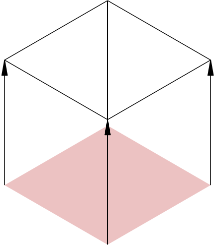
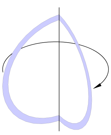
RotationA "rotation" is a 3D part that has been created by rotating a 2D surface or curve around a 2D rotation axis. Depending on whether the rotation outline is open or closed, the result will be either a 3D surface or a solid 3D part. Using additional offsets along and perpendicular to the rotation axis, the rotation can be extended to create solids such as springs and helixes. By explicitly stating the number of rotation steps it is possible to create polygonal rotation solids.
Examples for a rotation
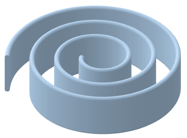
PathA "path" is a 3D part that has been created by moving a 2D surface or curve along a 2D path. Depending on whether the path outline is open or closed, the result will be either a 3D surface or a solid 3D part. By rotating the path outline around itself while moving along the path, it is possible to create "twisted" solids such as threads or springs.
Examples for a path
Freeform SolidA "freeform solid" is a 3D part which is basically a collection of arbitrary 3D facets. Such a freeform solid can consist of multiple subsets having different properties (especially colors). It is usually created as the result of an STL import:
Freeform solid from STL Import
A freeform solid cannot be disassembled, but it can be combined with other parts. Using a cylinder and the difference operator, e.g., a subsequent drill hole was added to the part displayed above:
Freeform solid with drill hole
Group of PartsA "group of parts" is an integration of multiple 3D parts into one new 3D part. The group of parts will be handled as one from now on, but can be disassembled into its components at any time.
If the integrated parts should penetrate each other, this will be displayed correctly, but unlike when using the union operator, the superfluous interior facets will not be determined and removed. As a result, such a group of parts is no mathematically correct part and has only a limited use as part of an operation. If necessary, the group has to be resolved and replaced with a union of all penetrating parts. Nevertheless, a group of parts is useful to combine parts in a way that they are displayed with correct facet sorting, but without the high calculation time required for an operator.
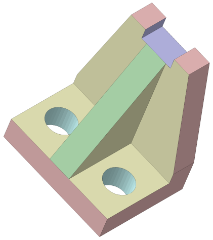
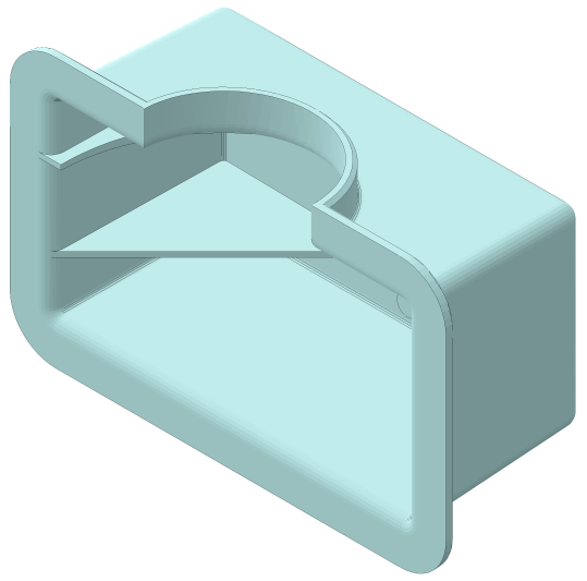
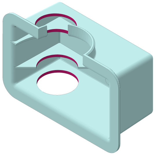
OperatorAn "operator" is a combination of multiple 3D parts into a new 3D part. The following operation types are available: Union, difference, and intersection. The result of such an operator is treated as a unit, but can be resolved into its components at any time. The following part has been created from a sphere, two cylinders, and two extrusions by means of multiple consecutive operator uses:
Step-by-step creation of a part by means of operators
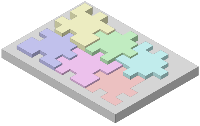
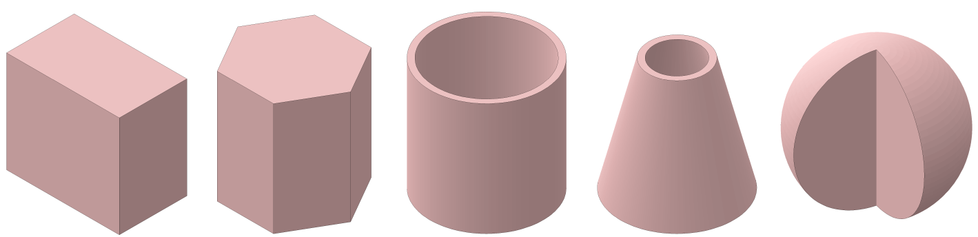
Standard PartA "standard part" is a parametrically determined, predefined 3D part. With that you can create may types of parts without having to strenuously create 2D intermediate outlines in order to create those basis forms. Here are some examples of standard parts:
Examples for standard parts
The parameters of the standard parts as well as their type can subsequently be edited at any time. As a result, the radius of a circle can be changed or a cylinder can be transformed into a hollow cylinder ("pipe").
3D BlockAll blocks in CAD6 that contain 3D parts can be inserted as 3D blocks. Special commands allow to insert 3D instances and to create pure 3D blocks. Within a library, both 2D and 3D blocks can be arbitrarily mixed. 3D blocks can also be inserted as a 2D block using the standard 2D command (which, in effect, uncouples them from the 3D world).
3D PointIf a command requires the entry of a 3D point during its execution, you can either identify a corner of a 3D part or a 3D construction point by clicking near to it. 3D points will always be snapped!
Alternatively, you can press the key for coordinate entry (usually F8 or ENTER) and enter the point’s X-, Y-, and Z-coordinate numerically in the appearing dialog. If multiple points are to be entered, the coordinate entry dialog window will be initialized with the previous point’s coordinates beginning with the second point. By adding to or subtracting from these values, you can easily enter relative coordinates.
Hopefully, you were already aware that you can directly enter mathematical terms such as "100 + 50" and "(200+30)/2" in any CAD6 dialog field expecting a numerical input?!
3D EdgeIf a command requires the entry of a 3D edge during its execution, you can either identify an edge of a 3D part or a 3D construction line by clicking near to it. In some cases it is not allowed to identify a construction line since it is endless and has no defined length.
3D FaceIf a command requires the entry of a 3D face during its execution, you can either click directly onto a 3D part to identify the front face at that position or near a 3D construction plane’s outline.
During the identification of a 3D face the current snapping radius will automatically be halved, i.e., you will have to click very near to a construction plane’s outline in order to identify it. This is necessary to minimize conflicts with the simultaneously possible identification of a 3D part’s face (by simply clicking onto the part).
|
CAD6studio Release 2025.0 - Copyright 2025 Malz++Kassner® GmbH