Coordinate System, Scale, and Unit (Introduction)
|
|
Coordinate System, Scale, and Unit (Introduction) |
www.CAD6.com |
|
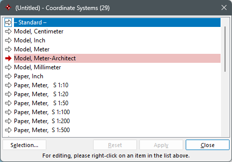
The coordinate systems determine the parameters which the program uses to process drawing data mathematically. You can set the coordinate system parameters via a dialog called with the command Manage > Coordinate Systems > Edit.
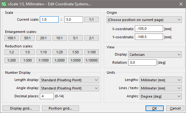
Edit Coordinate Systems
ViewThe view and the scale of a coordinate system can be adjusted in the left section of the "Edit Coordinate System".
Edit a Coordinate System
CAD6 distinguishes between four different views. The coordinate display is chose form the list "Display". This determines whether the objects should be displayed "normally" or "distorted".
Cartesian The objects and instances are shown undistorted. The aspect ratios and angles used on screen are the same as those used for output.
Isometric The objects and instances in the drawing are distorted, so that the respective view of an isometric/dimetric representation appears undistorted. These both display methods make a 3D-view possible in a simple way. Furthermore three distinguished views can be related. It is very helpful to work with several overview windows. Each one can display a different 3D-views.
The rotation angle for the coordinate system can be entered in this edit box „Rotation". One the most important components of a coordinate system are the scale. The scale determines the "real" size of an object, i.e. how large a drawn object is supposed to be in the model world.
Scales, Units, and DimensionsThe most important components of a coordinate system are the scale and the units. The scale determines the "real" size of an object, i.e. how large a drawn object is supposed to be in the model world. Using a scale of 1:20 means that an object whose length is 10 cm on the paper is supposed to have a length of 200 cm in reality. The view of a coordinate system can be adjusted by the dialog "View" (see above).
Above all, scales are influencing dimensions, i.e. dimension statements within a drawing. Dimension do always show the "real" size of an object based on the scale, and not its size on the paper. This is why each dimension is directly linked to a coordinate system, out if which is determines the scaling information. In addition, it uses the desired length and angle units stored in the coordinate system for the dimension.
If dimensions are to be linked to a specific coordinate system, this can either be done in advance by means of the Annotate > Dimension Parameters command, or afterwards by means of the Modify > Object Properties > Edit command.
The unit of a coordinate system can be adjusted in the right section of the "Edit Coordinate System" dialog.
The scale and the units do not only influence dimensions placed in the drawing, but all types of measurement, both during user entry (e.g. numerical input of a length) and during screen output (e.g. the coordinate display in the status window).
The user can choose measurement units (e.g. cm instead of mm) by typing the abbreviation for that unit after the figure. You can use this procedure in all dialogs. You can combine different units in the same calculation, e.g. "1 m + 13 cm".
Create a User-Defined Coordinate SystemBy using "New", the name of a user-defined coordinate system can be edited, which appears the dialog list. After creation the new coordinate system gets the default settings for the scale, unit, etc. of the main program. The steps described above must be performed.
The name of the coordinate system has not influence on the settings of the coordinate system, i.e. changing the name causes no modification of the scale.
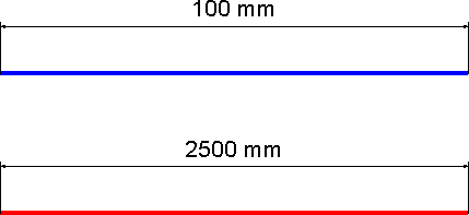
Multiple ScalesEach drawing can have several coordinate systems defined within it. The following figure shows two lines of a drawing. Although the dimension of the lines are different, when printing each lines have got a length of 100 mm. The lower line was drawn in another scale (Scale 1:25, mm) as the other one (Scale 1:1, mm). All dimensions are related to the current scale.
Dimensions with two different Scales
Changing the coordinate system does not affect already existed dimensions, i.e. the original scale are preserved. If the dimension is to change, the object properties of the dimension must be changed explicitly.
OriginThe origin of the drawing is the origin of the coordinate system as well. All coordinate entries as well grid setting are related to this point. The origin can be adjusted in the right section of the "Edit Coordinate System" dialog.
Edit a Coordinate System
The origin can be changed to a predefined position, or can be edited explicitly (see Draw Objects). By using Manage > Coordinate Systems > Origin, the origin can be edited via left mouse click.
|
CAD6studio Release 2025.1 - Copyright 2025 Malz++Kassner® GmbH