Example 6: Drilling with Drilling Cycles (CAM Introduction)
|
|
Example 6: Drilling with Drilling Cycles (CAM Introduction) |
www.CAD6.com |
|
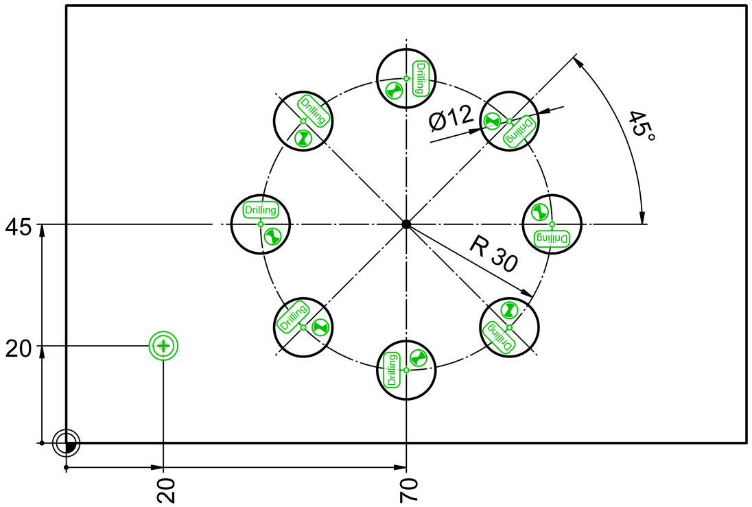
Sample Drawing: "CAM\Drilling with Drilling Cycles"
Export ObjectsThe objects to be exported are shown in green in the drawing. The associated NC blocks (lines) also appear in this color.
The objects on the circle with the center (70|45) and the radius 30 are each the block instance "Drilling Cycles\G200 Drilling" from the "CAM-Universal" library. In the object sequence, the first drilling cycle is at position (40|45), this was created with the Block > Insert command. The other seven drilling cycles follow clockwise and were applied using the Shape > Move / Copy Objects > Multiply Copy, Rotation command.
At position (20|20) is the block instance "Dummy Point" from the "CAM Universal" library. This dummy point is behind the last drilling cycle in the object sequence.
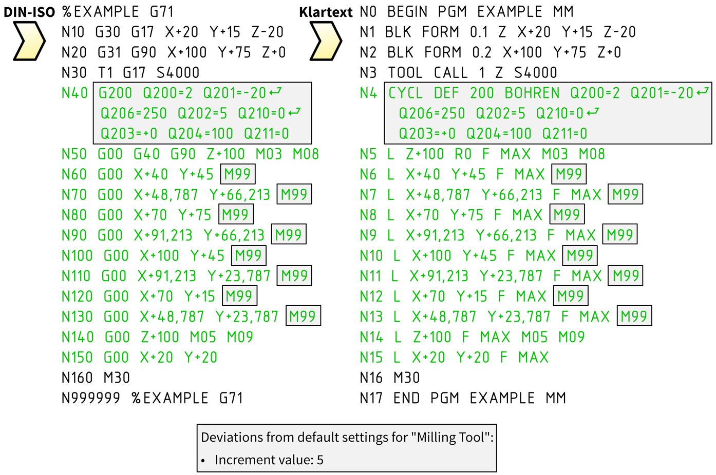
Drilling Cycles using CAM Block InstancesFrequently recurring processes that include several processing steps are saved in cycles. Many machine controls support drilling cycles, milling cycles or turning cycles, for example.
In CAD6, cycles are implemented with the help of block instances from the supplied "CAM Universal" library. The insertion point of the CAM block instance determines the position in the X/Y plane at which a cycle is performed. The commands for the respective cycle come from the attributes attached to the CAM block instance, the so-called cycle attributes. You define the base name of this cycle attribute in the postprocessor settings under "Object Control". For the postprocessor "HEIDENHAIN DIN-ISO (Milling)", for example, this is "DIN-ISO". With the CAM block instance "Drilling Cycles\G200 Drilling", the content of the cycle attributes "DIN-ISO_1", "DIN-ISO_2" and "DIN-ISO_3" is therefore copied to the NC file during the export.
Cycle G200 of a Heidenhain control (e.g. TNC 426) drills to the final Z depth of -20 with the plunging speed of 250 set in tool 1 and infeed depth 5 (further information on this drilling cycle and other cycles can be found in the Heidenhain user manual). The cycle definition (G200) is in block (line) N40. Before each cycle call (M99), the tool is moved to the relevant position in the X/Y plane. The positions, sequence and number of cycle calls are determined by the insertion points, the sequence and the number of CAM block instances "Drilling Cycles\G200 Drilling". The "dummy point" (20|20) is approached last; this contains an empty attribute "DIN-ISO", which means that no further NC commands are executed.
The objects that make up a CAM block do not affect the NC code in any way, they are only used for display on the drawing area. Also, scaling or rotating the CAM block instance is irrelevant for the export to the NC file, as this has no effect on the insertion point. If required, you can copy the "CAM Universal" library supplied, rename it and then expand it with self-generated blocks/cycles. We would be happy to help you generate the right cycles for your application!
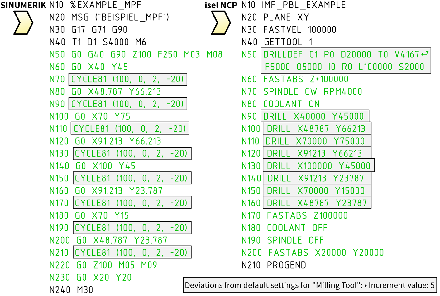
The CAM block instance "Drilling Cycles\G200 Drilling" contains cycle attributes for all post processors mentioned in this example. The drawing is exactly the same for every NC export. During the NC export, the program gets the information about which cycle attributes are to be used from the name for the cycle attributes, which is specified in the postprocessor settings under "Object Control".
This means that after you have opened the new postprocessor in the CAM > Edit Postprocessor dialog and always selected the same set of objects, you will receive the NC programs shown here without any further changes. It's best if you try this out for yourself! To do this, open the drawing mentioned above and the desired postprocessor. Then start the CAM > Export with Postprocessor command and select the objects (F10 key).
Information on the structure and parameters of drilling cycles can be found in the manual for your machine control. You can easily adapt the drilling cycle shown here to your needs by editing the associated block in the "CAM Universal" library (or in the copy you have created).
|
CAD6industrie CAM Release 2025.0 - Copyright 2025 Malz++Kassner® GmbH